2011-12-05

Change bicycle crank

Last winter during the two month long ice age I fell of the bike. I got stuck with the front wheel on a hiden tram track (under the snow I missed it). The fall was quite hard and one of the pedal crank arms on the Kronan got bent.
Since during the summer I've been taking Luísa on the Batavus and the Kronan was "ridable" I let it linger for a long time... and after much procastination and "planning" I decided to order online and replace the cranks myself.

There are several tutorials on the net (one here), and what is definetely needed in a crank removal tool and special recessed nut wrench, all the other tools are common workshop tools.
First remove the plastic cap hidding the bolt, then use the special recessed bolt wrench and remove this bolt.


The insert the crank removal tool in the crank nut and turn the extractor bolt, this will slowly move the crank arm out of the axel.


Then just remove the crank arm and remove the pedal (just the crank arm was bent, the pedal was unharmed).


Remove the pedal with a wrench.


Put in the new crank arm, screw in the fixing bolt and the old pedal, repeat for the other side and voila!

And now I'm ready for the harsh weather with the Kronan again...

2011-12-01

Luísa is two!

Luísa is two today...


We picked her up early from the daycare... she was not "thrilled" when we woke her up in the middle of her afternoon nap...
Well, we managed her to wave (reluctantly) after a few seconds... (Only after she insisted on getting on the bike :-)

2011-11-11

TI Launchpad

Recently I've been trying to do battery powered devices and I came to the conclusion that there is more to it than you first think.
My experience with the Bird-O-Matic is that it each battery lasted only 25% of what I had planed. There were some options that might have influenced it:
  • I didn't made an OFF timer, once the PIR detects an warm object it turns ON the MP3 player and the Amplifier for some time (7-10 seconds), placing a forced OFF timer of 20-30 seconds would prevent constant re-triggering every time someone passes by.
  • Was the use of a CMOS 555 better than a micro-controller? Today's controllers consume almost nothing in standby or power down mode, and a wake up on pin changed could be used with the PIR.
  • The external MP3 player consumes a lot of power and takes 1-2 seconds to start up. It was the simpler and fastest solution, but not the best for power saving.
Recently I read about the MSP430 ultra low power capabilities and I wanted to try them out. The Texas Instruments Lauchpad let's you do just that at a very low price (about 10EUR) and a big Windows installation (see here). I admit I'm always very reluctant to install windows software but unfortunately these links for installing in Linux didn't work out.


It is a bit sad, but I'm no sysadmin and no I don't know perl and I don't want to lose time learning perl, to correct a script, to install a msp430-gcc, to program devices... I understand the technical difficulties behind maintaining and supplying a gcc distribution (specially if also sell a payed tool), but nowadays it is becoming a "must". Sounds like when AMD started giving away PALASM... suddenly every PLD manufacturer started doing it or... went out of business..
After installing the correct tool (the free version is not the latest version), I followed the start up guide and sure enough I made my first C program.
The tool is simple and powerful (based on eclipse), in Windows everything works mostly out of the box.


The board is "divided" into a emulation tool and the experimenter board where devices of 14 and 16pins can be connected. There's also the option of soldering (an included) SMD low-power crystal oscillator. Instructions are also provided on how to measure the power of the experimenter processor, although it is tempting do not cut the board through the dashed lines.. it will not work as a MSP-ISP... that's another tool. (but I guess removing the jumpers and direct connection is ok :-).
The processor although a 16bit simple RISC architecture does appear to be quite capable, I just tried out a couple of examples in C. This though is not what I want to try out... I want to see if the operating current is as low as "advertised", but that will have to be for a another post.

Christmas Ball (the 11.11.11 post)

It is a bit late to announce but we won a prize!!!


Huyser bookstore in Delft ran a competition to promote the book from Arne and Carlos "55 Christmas Balls to Knit", see the promotional video here. Just before the deadline (1.11.11) our son Daniel was born, but we managed to find time to finish the Ball and submit it.
Naturally Ana chose a pattern and knitted the ball, I took care of the electronics. We were so late entering the competition that we only have "night shots" before submitting the ball...


It is a simple ATTiny15L powered with 3x AAA alkaline batteries.
There are 4 LEDs connected to the ATTiny, each in one of the reindeer's nose.
I've made a 32bit pseudo random number generator with a LFSR. The ball to lit is randomly picked (1..4) and also the fade-in time (1-2sec), fade-out time (1-2 sec) and off-time (2..4 x 2.5sec i.e. number of watchdog cycles).
The average measured power consumption is 1.5mA so one can expect about 1000 hours of operation from 3 standard cells.
(click on the circuit for a better view)


The schematic is not exactly this one, this is for another project that hopefully will come out before Christmas, just remove the solar charger, the voltage measuring and that's it!
We got the third prize, 100EUR in books!!!

2011-10-07

Balcony Crop 2011

Winter is coming and I almost forgot...
This year crops were not better than last year, and considerably less than the first year, the ground in the vases is getting "worn out" and too compact so vegetables that grow in the ground (carrots and turnips) don't grow that much.


Still we managed one (yes, only one) bowl of steamed vegetables (150g). This year Luísa helped picking up the carrots.
The "top of the crop" goes to the turnip followed by the micro-carrot.


Unfortunately, the beetroot did not survive the very dry and hot spring followed by a damp and lousy summer...
I'm now awaiting for everything in the vases to dye out and then I reinforce the soil or change it all together...

2011-09-28

FireFly Jam Jar

I wanted to build a night-lamp for Luísa, something a bit less "spooky" than a blue IKEA Spöka that she has. I also wanted to be able to charge just by placing it in the sun (even there isn't much of that up here)...
I went back to my stack of old ATTiny15L and designed a circuit with four LEDs connected in a particular way that only used 3 pins to lit each of them. The other two measure external light (light on when it is dark) and battery (low bat... do nothing be very very still).
I got some jam jars and some Yellow/Amber LEDs and started programming, for the battery I selected a 3.6V 50mAh NiCad (i.e. junk hanging around) and the battery charger was a two transistor current limiter but after some tries I settled with a simple schottky diode from the panel to the battery.


The idea of the project is that when night falls (or lights out) the light goes on for about an hour hopping from one light to the other with different ratios of fade-in and fade-out. This hopefully will induce a sleepy feeling (like candles... by the way.. simulating four candles is also possible)
The schematic is the same as for the reindeer ball project, but this time I went "all the way" to a PCB FAB. I still have to wait for it to come but it looks nice in the preview.


It is my first "non-rectangular" board and actually my first milled board. We'll see how this project will look like in the end...

Alex OpenTherm interface for JeeNode


Alex requested a "quick and dirty prototype" for his Opentherm JeeNode interface. He has more details on the "substance" here and here. I just made the boards, it is all his design (boards plural, the first one was wrongly mirrored, b.t.w. it is the wrong one you see on the pictures).
I followed the usual toner transfer method, and just works, HEMA photo paper is the best! The second board is not so pretty.... but at least it is correct (no photos of this one though).
The schematics are on Alex's site but here's my second try at the schematics also:


Here a detail of the board where you can see some "over etching":

Bird-O-Matic

Pedro asked me, some time ago, to do a collaboration project with a good friend of his.
The idea for the installation art project was the story "The Nightingale" from H.C. Andersen, the idea was to build/make a talking bird of sorts. Our initial plans had to change somewhat substantially... here's what we did:


My part, was to design and build the electronics that would "make the bird sing", we already had the bird's voice in a mp3 track (a danish Nightingale!!), we just needed something to play it. The original idea was to have a bird (just like in the story), but one of the places was an open air installation, so a bird cage seemed a better option.

The first constrain was time, we had only two months for doing the first "bird-o-matic". We gathered a PIR Sensor, a MP3 Player, and a LM386 amplifier IC from Solarbotics.
We wanted a reasonable sound volume so we chose a 9V battery to power the circuit, this is challenge because these batteries do not have a big capacity (max about 1000mAh) and we still wanted to play for some time without replacing the battery. This also excluded from the start using an Arduino as they consume a lot of current even if you manage to put it in standby.
I decided to use a simple monostable (LMC555) triggered by the PIR sensor that would activate the MP3 player and amplifier for a reasonable time (enough to play the nightingale sound). I used low-power MOSFETs for the power switching and one as inverter.
The first build used a LM78L05 but these have a very high quiescent current (~4mA), 10x more than the PIR sensor alone(~350uA)! The second choice was the LM2950 with only 40uA without load (increases to about the double with load) The LMC555 also has a lower quiescent current when operated at 5V (100uA) when compared to 9V (~160uA), and orders of magnitude lower than his "high power" counterpart the LM555.
Still the total current in standby was lower that 600uA, this would give 2000 hours in standby!
Playing... well "you can't make an omelet without breaking some eggs", the MP3 player consumed about 80mA and the LM386 another 80mA, giving a total play time of about 6 hours, still quite good if you think that the track was only 20 seconds... that is about 1100 times... it also exceeds the LM2950 maximum current by 50% but it works until it is too hot then the thermal shutdown "kills the bird" (battery saving on the cheap).
Here is the schematic:

Here is a close up of the inside of the bird cage:

Here a photo of the first prototype:

2011-09-16

New Boards arrived!

A month or so ago I bought a development kit of GreenPak from Silego. The parts appear to be very powerful for simple control tasks, I have a small Switch Mode Power Supply project but I wanted to try it out on a breadboard before committing to a full PCB.
The parts are tiny tiny and an adapter to DIP 8 was needed. I sent my mini design to lean and my boards are here! Here's the result!

2011-08-01

We're back!

Sorry all, we've been on Holidays and now we're back.

I have a couple of projects going on but one is "secret" and the other is... trash... I'm trying to make art out of trash (or making less valuable trash out of more valuable trash).
The secret is something for my loved one (that's why it is secret), the trash one is a mini-wind generator, another of the projects involves LEDs, batteries, Solar cells and a jam jar and some other bits and pieces... Something like this.


I've noticed that postings are running low, at one per month.. I'll try to increase that this month to two... as any statistician would tell you, "it's a 100% increase"!! (and this one doesn't count, I promise!)

Some other projects in my head are around analog electronics, I've studying a lot of transistor circuits (band-gaps, differential pairs, current sources) and special op-amp circuits (integrators, analog computers). I'll try to post something on the matter later.

I've been unable to stick with the "cult of done" motto, 15 days is almost nothing in my development cycles. I have a lot of "diaper change" in between and it's hard to get some spare time during the week.

Meanwhile I also lost my beloved Rotring Quattro... two months after the blog post! Now I can't get used to the new one... it was my precious... I got a "cheap" (read not cheap) Parker Multi-pen Executive for replacement... The Lamy 4pen only comes with a 0.7mm pencil and I can't write with those, they're just too thick, kind of grocer's pencil...

Well back to work and I'll write soon..

2011-07-02

SBC6120 with a teletype

Recently I bought a Teletype (a Texas Silent 700 model 703), it is special as it uses thermal paper and it is surprisingly silent :-).

I installed the light guides on the SBC6120 indicators, so now they are much more visible.

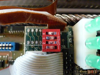
I had to replace an internal dip-switch and find a power supply for it, unfortunately I could not find a suitable power connector, for now it is connected with a pair of crocodile clips. The power input is AC-Earth-AC and a suitable voltage is from 20V to 26V, the current is about 1.5A.


The serial connection is at 300Baud surprisingly slow... 30 cps... This was how computers were operated before there were VDU (or CRTs as you prefer), it is very interesting. Next I'll try to install the Adventure game... The serial cable that came with the machine had to be tweaked in order to make it work with the SBC6120.


Here is a clip of theSBC6120 booting connected to the TI Silent.

2011-05-09

SBC6120 - Project Done!

It is done! My SBC6120 finally has a case that I am proud of. It still needs some finishing touches (namely some light pipes for the LEDS on the board to the front panel), but that's about it.


Since I haven't used it for quite some time I forgot some of the "intricate" details of working with it:
- I lost an incredible amount of time in a hardware bug that did not exist, simply because I forgot that the communication interface is 9600-7E1 and NO handshakes (hardware or XON-XOFF)... Minicom in linux installs default with hardware handshake, you see the boot message but you cannot write anything...
- and OS/8 only works with CAPITALS... (This is not a MAC OS8!, Mac friends look elsewhere).
To fit everything inside the Hammond box, I built a base in 1.5mm plastic and glued nylon screws upside down, these would fix the SBC on the lower part of the case, I've built a power supply board to convert 12V in the 5V needed for the SBC, finally I designed custom front and back panels.
I've built four prototypes of the front panel (in paper) and glued them to 2mm thick foam to get a look and feel of the panels before committing to fabrication. I used the services of Schaeffer AG for milling the front and rear panel, their (freely distributed) CAD program is actually very nice and it is available for linux! (I had some problems with sending the design but the drawing was actually all done in linux). It isn't cheap, but sure is top-quality.


The reset button does not protrude to the external of the box as intended, but having a "insert pencil here to reset" hole is not so bad (might even be a feature :-). Here you can also see why there's a need for a light pipe.


The slots in the back are enough for cooling the SBC6120 and the 3.5'' IDE drive, it takes about six hours to serially download two disk images, the boards and case never exceeded ambient temp by more than 20C.


The whole case is quite small (for a PDP-8), here's a top view, a fair view of what's inside is in an older post and here. The paper sheet below is A4 size.


The final photo just like in Sparetimegizmos is my the SBC6120 with an HP-16C side-by-side, just like the "inspirational photo" from their site. Yes, the calculator is more expensive than the computer :-).


Next... Install some adventure games... like this one... :-)
what's the use of a computer other than entertainment....

2011-04-10

The Calculator is dead, long live the Calculator...

My eyesight problem triggered a new blog motto... I must stay away from the computer when I'm "dedicated" to my home projects (or at least reduce the time to a minimum).
Here it comes "Never again use a Spreadsheet for designing power electronics"! I must admit that for work it is the best thing available,test scenarios, test components, circuit configurations everything numerical at a touch of a "button". But I don't need that, this is supposed to be for fun. I don't need speed of calculus, I want to keep learning the "Art". From now on calculations will be displayed scanned from the squared paper (I still have to find a scanner though)... And these two will have a bit more work...

Thinking back, how many times did I use a graphics calculator for a graphics problem? I don't remember, but not many...
I did love my HP48 in the last two years of university (before that I had a TI 57 II), I had to work for a while to pay for it and my father helped out with 50%.
Once at an exam, the teacher that saw my Texas classified it as "a Grocer's calculator", that was really embarrassing and this was in 1997!(most of my colleagues had either an 48S, the 48SX or the Casio Computer 850??)...
The HP32S was bought recently in Epay, to get something a bit more "portable" and keep "playing" outside...

2011-04-09

Pen Life - Rotring Quattro

When these pens came out I could not afford them, they costed about 50EUR (in today's money something like 80EUR) and they looked great... Geeky and Engineer like. As soon as I started working and received my first engineering salary I bought one. Recently I found one (new old stock) in Epay... here are the two, side by side, check the differences...


There's another difference that I didn't even remember... when I bought it the finishing was black matte and kind of "rough" or "sand" paint, with 15 years of use that is all gone.
One not so good side of the pen was that the main writing refill would not last long enough (during meetings I tended to write a lot, not anymore though) and the marker pen was "inconsistent" when you wanted it to write. (here's a product review for a product that does not exist)...

New Crops 2011

Spring is up, time for some new balcony crops! This year, broccoli, turnips and carrots.. They're already sprouting (due to the fantastic weather we've been having in The Hague...
These are my carrots for this year (the clay ball is 1cm diameter).

Just noticed that I need to clean the lens, probably the "little camera devil" touched it...
This is a beetroot that survived the winter.

Hopefully it will grow to "edible" size in these next few months.

SBC6120 - Power Supply Board

It had been planed for ages, but I never had the time or a technical "consideration" delayed me. I finally decided to just do it (after reading the "cult of done" manifesto), the board with the Laser Toner Transfer and HEMA inkjet photopaper, this was probably the biggest board and with the least detail I've ever done (160x120mm).

The board needed only to fix the connectors, the power switch and a switching power supply. I didn't have much space available on the top side, so I went through my "pile of components" and found a couple of single IC switching power supplies (the National LM2575-5V), I also had a SMD version of it (or so I thought) and some SMD Schottky diodes. The board is also used to mechanically fix the 3.5 inch Harddrive.


The schematic was simple, just the switch, the connectors and the switcher, I added a turn on delay to let everything power up slowly (see the LM2575 datasheet).


The power switch (and the lever) are from C&K, but I had to buy an "old lever" as the new levers are much wider than what I could "afford" in terms of space on the front panel (there's no bezel for this older one though).
For the PCB I had some problems, but mostly mechanical. You can only see them when I show the pictures of the completed unit. I had to fit a 10mm inductor in a 10mm space and a 3.5 inch harddrive in 3.5inch (minus 1mm space, there's a screw on the harddrive I had to remove, otherwise the top would not close.

This is probably the only reason why I'll do boards at home, it must be a big board (>160mmx100mm), few tracks and single side, if it misses one of the tests, I'll go for a Fab. board.
After assembly... it didn't work... A quick trouble shooting revealed the cause... poor eyesight.
I had a LM2595S not the original LM2795 with which I drew the schematic and PCB. The pinout is very different. Then I found out I had no LM2975 SMD version. I had to improvise, a through hole package with bent leads and plenty of flux later...


After that mishap, I mounted everything back up and it worked. I formatted the drive and downloaded a disk image and now my SBC6120 boots!


It was done in two weeks! I'll try to keep this "cult of done" thing going on (but some of the tasks need to be broken in more than a couple of weekends).

2011-03-05

Tot Ziens Stuut en Bruin

Last 26th of February one of the most iconic Electronics shops in the Hague closed its doors after 63 years... Stuut en Bruin you'll be missed. After two months open in 2011 (and some nice IC sales), they finally gave in to modern trends and closed the shop.


The picture above was take on the last Saturday, where the sign "there's still 1 day" was on the window.

Here is the google.maps picture

View Larger Map
We are now left with two other shops that are more focused towards other fields (satelite and consumer electronics and electronic/electric spares).
It is sad... but life goes on...

2011-02-05

Chillies in the Wok

Finally it was time to eat my first chilli of the year! I let my jalapeno/piri-piri hybrid ripe until it was almost all red and then... to the pan with it.


It was not very big nor powerful, but a decent chilli!


Sliced and Wok with it...


Here's the dish next to the little Chilies vase...
Shrimps, Chillies, Peas and Udon noodles in the Wok are always a winning combination... Om nom nom!

SolarLight (9) - Powersaving Software

"It ain't over till it's over"... After a week of very cloudy days and mostly no charge, I found out that I needed to save more power and provide some late "adjustments".

The findings and solutions were:
- having a status output every watchdog reset was too much, too often (once every 8 seconds). A more reasonable status output is twice every minute. Displaying the status spent about 0.5% of the total battery capacity, but after an almost full discharge the lamp would only operate for another 2 or 3 days without recharging (i.e. a week of cloudy days was "deadly").
- even during the status display the CPU could be put to sleep during the status output (without using a timer but the watchdog).
- the detection of an external supply had to be changed from above 4.2V to above 4.0V, my external adapter would "kneel" to this voltage when the batteries were depleted.
- the output power levels function of the battery voltage also had to be adapted, even at the lowest level (around 200mA output) the battery voltage "kneels" quite deeply. So in order to take the most of the batteries I reduced the power output once the batteries are in the lowest charge (below 1.1V per element).
- another finding (with no solution as of yet) was that with AVRDUDE I cannot program the oscillator calibration value in FLASH (or EEPROM) automatically (as in AVR Studio). I'm not very "experienced" in script programming or makefiles with scripts but it must be possible. I need to program the flash with the code, then read the oscillator value and finally overwrite the flash (or write in a EEPROM) position where the code is getting this value. Since my program depends on this value for the switching power supply, I cannot be too away from the standard frequency of 1.6MHz.
Meanwhile I also updated my system to OpenSUSE 11.3 (yes, I know the new one is out... but I prefer "stability" over "bleeding edge").
The new code is pasted here
Ta Da for now!

2011-01-15

SolarLight (8) - Plastic Fixing Rig et altri.

In the new year I decided to further develop my SolarLight, I had to build a rigid rig to hold the light over my peppers vase. After some thought I decided to use plastic (polystyrol) to keep it lightweight. I used standard PVC glue (used for water/sewage pipes or spudguns) and Polystyrene.
To cut the boards I used standard hand tools (hand saw, metal file and sandpaper), thinking back I would be better off if I had used a table saw... With a good saw and speed setting I think I could do it all in one. I don't have a table saw, nor the space for it, maybe I'll use the Dremel mini-saw adaptor (Dremel 670) or one of the Proxxon mini/micro table saws.
The glueing of the parts was fast and clean, if you do something like this remember to do it out in the open or in a well ventilated place, toxic fumes come out while the parts are being chemically soldered. I found most of the plastic sheets and profiles here.


I started out by trying one of the few available 2D-CAD packages for linux, I used QCAD community edition that had a pre-compiled for my OpenSuse11.3 in the contrib repository. Learning a new tool has always it's steep learning curves, but I got what I wanted. I will try to use it for my future mechanical drawings of cases and front panels.


After the assembly I noticed that I forgot some openings for the LED connector and fixing, so it is just hanging for now. I also changed the battery pack I had for a 3x AA NiMH 2300mAh batteries. This was a mistake, the solar cell was selected based on a battery capacity of around 700mAh (an old NiCd pack I had laying around) and size of the board. Although with the batteries charged I got a good hour and a half of light, the next recharge period was a full week... from this page I would need 40 hours of sunlight to fully charge the battery as the solar panel output current is below the C/40 ratio... Taking into account that the average daily sunlight time of about 8h,(and in my south facing flat it's reduced to 4-5), that in Holland the sky is mostly cloudy for days in a row, that the solar cell outputs roughly 15mA with direct sunlight, I could expect to have a fully charged battery (with the NiMH pack) every two weeks.. With the NiCd I could expect once two sunny days (more or less what I was looking for). So I have to go back to smaller batteries, probably another junk 3x AAA NiCd pack I have around.
I also roughly measured the efficiency of power supply and made some tests. The maximum output current I managed was 700mA, more than that and the battery voltage would hit the under voltage protection I had built in, this is about 50% of the LEDs Power. I also had to add a heatsink to the LED as its temperature was rapidly increasing beyond the "can you touch it" capability (a rule of thumb I learned...). So I used a stable DC power supply and varied the input voltage, input current, output voltage and output current at about 25% LED power level (3.2V@300mA). The results are a bit disappointing, the efficiency is about 50% from the calculated 70%. I don't think the losses are semiconductor related but mostly the passive components (inductor resistance and capacitor inductance and resistance). The good point is that output voltage is mostly independent of input voltage...
I also did some improvements on the code and ordered some new SMD components, I'm planing on building a SMD version and extend the project to a bike light (with the electronics inside the lamp's casing), we'll see how that goes, later I'll publish the updated software.
I included a graceful degradation system to reduce the output power as the battery depletes its charge, the processor now sleeps between ADC conversions both to save power and reduce noise (I cannot disable the Timer as the PWM must run), I changed the charging process but not counting the hours of charge but only by checking the battery voltage as this allows an external charger (not sun) and finally I converted the code to be compile in linux (avr-gcc/gas).
It's a long post and I have some more post hanging in for further editing.. I'll try to keep up with one a week and I'm already falling behind.