Showing posts with label Solarlight. Show all posts

2011-02-05

SolarLight (9) - Powersaving Software

"It ain't over till it's over"... After a week of very cloudy days and mostly no charge, I found out that I needed to save more power and provide some late "adjustments".

The findings and solutions were:
- having a status output every watchdog reset was too much, too often (once every 8 seconds). A more reasonable status output is twice every minute. Displaying the status spent about 0.5% of the total battery capacity, but after an almost full discharge the lamp would only operate for another 2 or 3 days without recharging (i.e. a week of cloudy days was "deadly").
- even during the status display the CPU could be put to sleep during the status output (without using a timer but the watchdog).
- the detection of an external supply had to be changed from above 4.2V to above 4.0V, my external adapter would "kneel" to this voltage when the batteries were depleted.
- the output power levels function of the battery voltage also had to be adapted, even at the lowest level (around 200mA output) the battery voltage "kneels" quite deeply. So in order to take the most of the batteries I reduced the power output once the batteries are in the lowest charge (below 1.1V per element).
- another finding (with no solution as of yet) was that with AVRDUDE I cannot program the oscillator calibration value in FLASH (or EEPROM) automatically (as in AVR Studio). I'm not very "experienced" in script programming or makefiles with scripts but it must be possible. I need to program the flash with the code, then read the oscillator value and finally overwrite the flash (or write in a EEPROM) position where the code is getting this value. Since my program depends on this value for the switching power supply, I cannot be too away from the standard frequency of 1.6MHz.
Meanwhile I also updated my system to OpenSUSE 11.3 (yes, I know the new one is out... but I prefer "stability" over "bleeding edge").
The new code is pasted here
Ta Da for now!

2011-01-15

SolarLight (8) - Plastic Fixing Rig et altri.

In the new year I decided to further develop my SolarLight, I had to build a rigid rig to hold the light over my peppers vase. After some thought I decided to use plastic (polystyrol) to keep it lightweight. I used standard PVC glue (used for water/sewage pipes or spudguns) and Polystyrene.
To cut the boards I used standard hand tools (hand saw, metal file and sandpaper), thinking back I would be better off if I had used a table saw... With a good saw and speed setting I think I could do it all in one. I don't have a table saw, nor the space for it, maybe I'll use the Dremel mini-saw adaptor (Dremel 670) or one of the Proxxon mini/micro table saws.
The glueing of the parts was fast and clean, if you do something like this remember to do it out in the open or in a well ventilated place, toxic fumes come out while the parts are being chemically soldered. I found most of the plastic sheets and profiles here.


I started out by trying one of the few available 2D-CAD packages for linux, I used QCAD community edition that had a pre-compiled for my OpenSuse11.3 in the contrib repository. Learning a new tool has always it's steep learning curves, but I got what I wanted. I will try to use it for my future mechanical drawings of cases and front panels.


After the assembly I noticed that I forgot some openings for the LED connector and fixing, so it is just hanging for now. I also changed the battery pack I had for a 3x AA NiMH 2300mAh batteries. This was a mistake, the solar cell was selected based on a battery capacity of around 700mAh (an old NiCd pack I had laying around) and size of the board. Although with the batteries charged I got a good hour and a half of light, the next recharge period was a full week... from this page I would need 40 hours of sunlight to fully charge the battery as the solar panel output current is below the C/40 ratio... Taking into account that the average daily sunlight time of about 8h,(and in my south facing flat it's reduced to 4-5), that in Holland the sky is mostly cloudy for days in a row, that the solar cell outputs roughly 15mA with direct sunlight, I could expect to have a fully charged battery (with the NiMH pack) every two weeks.. With the NiCd I could expect once two sunny days (more or less what I was looking for). So I have to go back to smaller batteries, probably another junk 3x AAA NiCd pack I have around.
I also roughly measured the efficiency of power supply and made some tests. The maximum output current I managed was 700mA, more than that and the battery voltage would hit the under voltage protection I had built in, this is about 50% of the LEDs Power. I also had to add a heatsink to the LED as its temperature was rapidly increasing beyond the "can you touch it" capability (a rule of thumb I learned...). So I used a stable DC power supply and varied the input voltage, input current, output voltage and output current at about 25% LED power level (3.2V@300mA). The results are a bit disappointing, the efficiency is about 50% from the calculated 70%. I don't think the losses are semiconductor related but mostly the passive components (inductor resistance and capacitor inductance and resistance). The good point is that output voltage is mostly independent of input voltage...
I also did some improvements on the code and ordered some new SMD components, I'm planing on building a SMD version and extend the project to a bike light (with the electronics inside the lamp's casing), we'll see how that goes, later I'll publish the updated software.
I included a graceful degradation system to reduce the output power as the battery depletes its charge, the processor now sleeps between ADC conversions both to save power and reduce noise (I cannot disable the Timer as the PWM must run), I changed the charging process but not counting the hours of charge but only by checking the battery voltage as this allows an external charger (not sun) and finally I converted the code to be compile in linux (avr-gcc/gas).
It's a long post and I have some more post hanging in for further editing.. I'll try to keep up with one a week and I'm already falling behind.

2010-02-27

SolarLight (7) - Software, AVR assembly


Ok, finally google docs supports any type of file so I can post all the project files in one place: code, gerbers, gEDA design files and spreadsheet with the calculations, requirements. It is all here.
I decided to try out pastebin, so I'm updating this post with the code for everyone to take a peek... In this version I'm still working on the "when to turn on" routine, I think it still doesn't work as I initially intended... pastbin doesn't look so good to paste long assembly lines, but here it goes anyway..

The software as it is now is working, it has some problems and "room for improvement" but it is working! You know the motto: Make it work, make it better!, make it faster!

One of the improvements would be to limit the time the light is ON to about 30min-45minutes, this would allow the battery charge to progressively increase during the good sunlight days and progressively decrease on a sequence of bad sunlight days (as in this year for example).
Other improvement could be a full darkness detection and adjust a 12h no light clock from there. It has happened that during the day when a big cloud (and/or heavy rain/heavy snow) the measured light level goes down to the "night" level, then if there's enough battery the light turns on... it shouldn't and I'm sure this winter is exceptional, but the only way to prevent this is to detect the lowest darkness point and count 12 hours from there, and only from then on the light would turn on when it is dark.

In the code I added a debug routine that is included when the two variables are uncommented (DEBUG and DB_CNT), when I wanted to output a value I load it in the DEBUG variable and call dbug. The byte is output in the status LED serially MSB first, there is a long (2 cycles) high pulse followed by clock and MSB data, clock and bit 6 data... clock and LSB data.

Finally my biggest problem was the branch instructions, the AVR has the following:
BRLO - Branch if Lower (UNSIGNED)
BRLT - Branch if Less than (SIGNED)
BRGE - Branch if Greater or Equal (SIGNED)
BRSH - Branch if Same or Higher (UNSIGNED)
I was not used to have these complex branch instructions, I'm used to Zero Flag set, Zero Flag Clear, Carry set, Carry clear... I'm specially not used to having a different branch for signed or unsigned... So I chose wrong.. result the jumps were not taken when they should. The ADC values are unsigned when read (0..255) but if you start calculating with them you can get signed (negative) values and then you have to use signed instructions.
AVR assembly programmer beware!

A final word about the Code, it was assembled with Atmel AVR Studio Assembler (Win), it doesn't output the number of cycles per instruction... a bit of a let down... :-)
And with this post I finish this project.... Woo Hoo!! Project is dead, long live the new Project...

SolarLight (6) - PCB Fabrication and Assembly

Using gEDA for producing gerbers turned out to be easier than I thought.
Recently the gEDA project has been under fire in slashdot due to its "complicated", "non intuitive interface" and lack of documentation. I really don't think that the documentation is that bad, it is scattered but it is not bad, just look here. I haven't meet an Open Source project that didn't suffer from the same problem, even (and particularly) the GNU tools. As soon as you get out of the mainstream gcc/gas/ld/gdb you're almost on your own, searching bits and pieces in the internet. Some of the best GNU project documents have been written by a commercial enterprise (either redhat, cygnus or other).
I call it Anarchic-Knowledge (or Anarco-Conhecimento in Portuguese), everyone omits to write what he finds trivial, forgetting that what is trivial to him, might not be for the community that will use the product. Then a plurality of tutorials, blog posts and guides show up, each one showing how they did it "their way". A new user has to pick all these pieces, try more than one and finally write a "I did it my way" post... And we all learn from this experience.It is not the lack of documentation, it is just the way that Open Source grows.
Back to the how I did it... :-)
I followed this tutorial, I had a single page schematic so it was easy to generate the netlist. I created a single project file with the schematic libraries, I used my own symbols since not only I wanted to learn how to do them but also I had a MOSFET with two Drain Pins that I could use each in an independent circuit. I used shell scripts to get the job done, I tried once a Makefile but I realized that I would have to change the Makefile for every project (even smaller ones), a shell script can do that at invocation time.
I also created some Footprints for my project (also for educational purposes), I had them in a library directory and used jcl's gnetlist invocation but with my directory instead. PCB must also be configured to have a pointer to your library in the "File-Preferences-Library".
First follow what gschem2pcb tells you to do, open the file, import the parts, spread them and execute the command, then I put in most of the mechanical details, using the outline layer in a place where no components were place, size of the board, cuts, groves and fixing holes. Also check now for the DRC tolerances in the File-Preferences Menu.
Then the fun begins, it is a very iterative process: place, route, looks good? can I do it better? with less vias? other mechanical problems? heat sinks/problems? repeat until satisfied with the design.
Then I place some more information on the silkscreen, plus signs on the connectors, output indication, board reference, moved the references so that all are visible when the components are soldered and facing the same side (so that you don't need to rotate the board to read the references). I also place on the top and bottom layer a square with the layer number inside, so that you can identify the layers on the gerbers and on the boards.
I was going to use Olimex pcb prototype services for my first gEDA boards so I needed to limit the number of drill sizes, they have some drill sizes that are considered standard and any other is considered extra (and you pay more), luckily someone from the gEDA-user group already made a drill mapping file for Olimex after executing the script run DRC again! Here's my final PCB result.
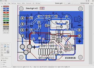
You can also export to png the two sides of the board in a "photo-like" picture, some people claim it gives better reading and it is easier to spot errors.

If you have no errors in the last DRC you're ready to produce your gerbers, and this part is as easy as pressing the correct button in export. Then with gerbv, check if the gerbers look nice and the drill sizes are correct.
Recently a good question came up in the geda-user mailing list, it sums it up nicely but the first reply reminded me of something I didn't do and should have done...
Print out your surface copper layers and put the parts on the printout to make sure they match.

yup, I designed my resistors with a 1/8W in mind and then I couldn't find any I had to use 1/4W.. so the resistors didn't fit in place. My DIP 4 for the MOSFET also didn't had big enough holes, apparently International Rectifier didn't stick to the normal DIP drill sizes, probably due to current capability or thermal conductivity. In that point, with some hindsight, I would increase the copper area connected to the drain, that could be a good heat sink for the MOSFET. I also should have thought a bit more on how to fix the board to the pole, with the new batteries the SolarLight is much heavier, I should have devised other way to fix it. Here's the board in place, note the resistors in two layers.
UPDATE: The resistor that is hanging and has two sockets is the gate resistor of the MOSFET, if you check the spreadsheet with the calculations you can see that the gate current has great influence in the MOSFET power (losses), so I made it low enough to still allow programming easily (now at 100R). When programming the micro the light turns on, but without any damaging effect as long as the frequency (of programming is high enough 250k) and the pattern is sufficiently random (see here for a bigger problem with ISP port sharing).


One last remark, if you buy microcontrollers in ebay and they say "New, Old Stock" it doesn't mean that they are not programmed, they can be factory programmed and that doesn't mean that they are not new! In case of the ATTiny15L, the low voltage programming mode can be disabled by this factory programming, if you solder it to the board you'll not be able to reprogram it. You need to remove it from the board and use a HVProgrammer like AVRDragon for example. Learned the hard way...

2010-02-17

SolarLight (5) - PCBs!!!

I finally had the time to pick my PCBs at the mail. I was thrilled to see who it went... My first linux made PCBs!
Everything went ok, except for a few minor point where I'm the only one to blame...
Here are the pics to the solarlight board and the others, the last one is the RFadaptor that didn't go as well as I expected, but I'm the only one to blame....
Here is the one where the wholes are just the size of the pins (just not enough for them to get through)...

I'll post how to get from PCB design to send them to Olimex (for example) for production. It's not that difficult but you need to follow some steps.

2010-01-30

SolarLight (4) - gEDA, PCB and first corrections

It has been a while since my last post, but I've been busy... not so much on electronics projects, but projects of other kind... Nevertheless I've been working a bit on SolarLight.
The prototype was working to light the LED but some other bits of the code were not working. Although the "light-on" function was working, the function checking the battery and checking the charging were not.
After wake-up from reset (power-up or watchdog), the micro checks if the current Solar Panel voltage is >200mV than the battery (a safe assumption it is charging) and if so increments a "charging timer", if this timer is less than 3hours, don't turn the light on. This is to be sure that there is some charging before a discharge. These and other checks were not working.
De-evolution from C to Assembler is always a mess if you have to re-learn the mechanics of each architecture. It is not only the instructions, its how the micro "thinks", only then you really control the machine.
On the hardware side I also had some problems, due to the limited number of pins I had to share some pins with the in circuit programmer, one of them is the MOSFET gate. I forgot to add a gate resistor to the source, in common MOSFETs with 10V gate threshold that is still asking for trouble, I guess that with LL (logic level) gate thresholds of 2V it is just "waiting to happen"... although it did take a couple of weeks...
I guess what hapened was, after programming the AVR-ISP left the pin floating and probably before that the level was high... the MOSFET kept on and finally burned.. I saw smoke coming out...
Here the new schematic with revisions on the lower corner.I also started the PCB design (with PCB part of gEDA suite) and I've now finished the board. It is not as packed as it could be because it has the size of a 3xAA pack. It is marked version 1.1 because I had finished the version 1.0 when the MOSFET blew up. I've mostly followed the tutorials available at the gEDA Documentation site:
- this one for the drawing of schematic and creating the netlist;
- this one for drawing footprints and getting to know PCB;
- and this one for the simulation;
- I also used this one for creating large "box symbols" (cpu, uart, etc)
I used gschem directly to create the new MOSFET symbol (IRLD024), since the original MOSFET symbol was graphic I though it would be better to use it instead of having a 4 pin box. I also wanted to keep both Drain connections separated if needed to use them in separate nets (although they are connected).
Using gEDA is still far from trivial as components, footprints, schematics symbols are all your responsibility, but still, I'm starting to like it. PCB also has a nice feature, you can print "photo mode" version of your PCB (yes, I know other software produces 3D views), here's mine top side.

2009-12-19

SolarLight (3) - First Prototype


Well after the initial breadboard, I decided to do some extra work on the Solarlight. I built a perfboard/smd board prototype and as usual I had to do some "adjustments".
Since my ATTiny45U in DIP are "precious" I wanted to use instead one of my ATTiny15L that I had around (a previous buy in ebay).

There are some major differences between the Tiny45 and the Tiny15L:
- Software - the Tiny15L does not have RAM and has a fixed length stack (3), programming it using avr-gcc is difficult and involves "tweaking" the code (see more here). The Tiny15L also does not have the debugwire interface, so debugging is a bit more difficult. Therefore I decided to develop the code in AVRStudio in windows (bah!) in assembler, as much as I like linux the simulators available are still far from perfect. One final remark on the simulator in AVRStudio, always read the notes about your processor, in the case of the ATTiny15L the watchdog is not simulated and the noise reduction sleep/wake-up on ADC conversion complete is not simulated!!
- Hardware - the pins and ADC input PB3/PB4 are switched (mentioned here), the ADC converter internal reference is fixed to 2.56V (ATTiny45U has 2.56V and 1.1V), the ATTiny45U has more power saving options and the frequency of the maximum PLL frequency (important for a high speed converter) is higher on the Tiny45 (8x8MHz=64MHz) than on the Tiny15 (16x1.6MHz=25.6MHz), the CPU clock also higher on the Tiny45 (8MHz) against the Tiny15 (16MHz).

The light is working but there are still some software issues to solve. As I mentioned the ATtiny15L does not have the debugwire interface, in order to debug the project I decided to encode data in the status LED as a bit-banged serial port (like this one), when I want to see a value of a conversion or get a check point or value, I change the code and wait for it to show up on the scope.
I also decided that I had to have a way of forcing a full light mode and a half light mode (both independent of the battery and charging) in case I connected the light using an adaptor (no solar light mode). For this I thought of using this same status pin, curiously this pin is placed between VCC and GND in the programming connector, so a simple jumper could activate these modes in the final product.

2009-11-27

SolarLight (2) and gEDA simulation

An update over SolarLight, I finally managed to print waveforms from ngspice in OpenSuse 11.2 . For some reason the interface is not what you would expect and it has become much more complicated to print a waveform than before.
The first time I installed gEDA from the sources (under OpenSuse 10.3), now I'm using a precompiled version from the OpenSuse Science repository, it could be that the precompiled version has the printer interface "disabled" in some way.
Back to waveform printing, under ngspice one would follow the following path to simulate and plot a waveform:
tran 100n 1.5m
plot v(501),v1000#branch

In the case of the SEPIC circuit of a previous post this would run transient simulation until t=1.5ms with a minimum time step of 100ns (try not to have more than a few thousand simulation points), the second line would open a new window with the output voltage and LED current displayed.
Previously when I pressed in the hardcopy button the print interface would appear and I could chose the printer and/or print to file. Now a message appears in the console:
The file "/tmp/hc4803" may be printed with the Unix "plot" command,or by using the '-g' flag to the Unix lpr command.

If you try the "lpr -g" command either the system complains that it is not supported or that no printer is installed.
lpr: Warning - 'g' format modifier not supported - output may not be correct!
lpr: Error - no default destination available.

After installing plotutils I managed to convert the plotted file (hc4803) to almost any known format (for example postscript or png) with the command:
plot --output-format ps hc4803 > hc4803.ps
plot --output-format png hc4803 > hc4803.png

This allows the plots to be printed and included in documents or webpages, the plot looks something like this:

Then I wanted to try out gwave, gwave is a waveform viewer, part of the gEDA package but its use is far from trivial. First in gwave you must run a simulation and then write the data to a file:

tran 100ns 1.5ms
write plotdata.dta

then run gwave with this data.

gwave plotdata.dta

The interface is far from trivial, I was unable to use colours for the plot and I also had error while trying to print a plot, but at least I could see some waveforms. Results may vary depending on your installed system, but here is a screenshot of the program, the waveforms are in gray on black background:


I'm now temped in building the gEDA toolsuite from scratch... but for that I need some more time...

2009-11-22

SolarLight

Some time ago I had the idea of building a LED lamp that was solar powered, harvesting the Sun during the day and charging the battery, while at night deliver some light. The idea was to extend the hours of light of my peppers during the winter, once the vase was inside the house.

For the initial design I wanted to use two old Ni-Cd batteries and for this supply voltage I would need to use a low voltage oscillator circuit as the minimum voltage would be around 2.0V. The converter would be a boost converter since the Luxeon K2 I had were rated for minimum 2.79V. I started by using a general Boost converter design procedure, and then simulate the circuit in gEDA/SPICE/ngspice.


I stumbled in two problems:
- after some tries with simple transistor oscillator circuits, low voltage comparators, and PWM modulators I decided to use a micro-controller. The biggest problem was the low voltage, even the low voltage circuits shut-down at 3.0V. Then I decided to use a low-voltage micro like the ATTiny45U capable of operating from 1.8V.
-The booster wasn't working, the LED was conducting slightly when the oscillator was off, a known problem with boosters, if the load consumes power at the input voltage minus a diode drop the circuit is always draining the battery.

Finally I decided to redesign the circuit using a 3 element battery, this time a scrap battery from a mobilephone Li-Mh with 3.7V, this would ease the micro selection (Attiny15L that I used before) and I had to change the type of converter to a SEPIC, that allows the use of a battery with a voltage close to the LED conduction voltage. The circuit has the advantage of being capable of boosting or dropping the input voltage, this application note and this one are quite useful for the design phase. Since the load is an LED I allowed a bigger fluctuation in the inductor currents and of the output current, then I chose the operating frequency function of inductors I had available.

Again, after calculating the circuit components I drew a circuit in gEDA and simulated the circuit. As a general design procedure the circuit I use to simulate is very different from the one that I'll build in the breadboard/PCB.

I placed some components inside green boxes to simulate real inductors with series resistance and real capacitors with series resistance. The voltage sources with zero voltage in some branches allow measurement of the current in the branch. I could not find the correct MOSFET (IRLD024) model, instead I used the model (IRFD024) of a similar one but with a different Gate Threshold Voltage. Also as a common procedure to minimize size of the files and speed up processing, I create a smaller library file, containing only the models used. I wanted to show a waveform but since I updated my OpenSuse install to 11.2 I'm unable to print ngspice plots...

After verifying that the circuit worked, I designed the final schematic with the micro-controller and the voltage dividers of the various analog inputs.


The software was straight forward, start the high speed oscillator, start the PWM generator, read voltages, take decisions and increase/decrease PWM output. One note worth mentioning is that the ATTiny85 and the ATTiny15 have two input ports exchanged (Port PB4/PB3 - Pins 2/3) although the ADC inputs are the same!
Here is a couple of pictures of the circuit, the first charging and the second working.