2010-10-28

SMD help

I sometimes boast about my old SMD soldering skills to my "happy hacking" friends... It's quite safe, until someone actually asks you to do _this_! Alex bought some of these JeeNodes from JeeLabs and needed some help. I accepted the challenge...
Before we start, a word of wisdom... Don't try this at home if you don't have the right tools, if you are uncertain about your tools or your ability it is best to send the module to JeeLabs and he'll repair it for you.
Following the site it is easy to understand the problem, Vout and Vin are connected to the wrong sources (this is a linear regulator Vout must be lower than Vin). The solution appears easy but it was not clear from the pictures, once the IC is in the vertical, there are two sides to chose from.
I usually start with the board to repair over a clean sheet of paper, makes easier to see as there's a better contrast, also if some small components come off the board or need to go in they're easy to see.
I then apply a small blob of solder to each side of the IC. The blob keeps liquid for some time and allows you to heat the other side (it must be a quick movement), once both sides have liquid solder slide the IC off the PCB to the paper.
Then using solder-wick clean the excess solder on the pads and on the IC feet.
I then marked the pads and the IC feet with the numbers and visualized what I had to do.
The IC actually is placed in "dead bug" style (but sideways), this means that the IC is "top-to-bottom", it is not so clear in the JeeLabs pictures.The mechanical pencil is 0.3mm for reference.
Finally I used some wire-wrap wire to connect the "floating-pad" to the board.
Since I have no idea how to connected to the JeeNode, connected it to the USB port and checked if the output voltage was around 3V... Some LEDs blinked (like in Arduino's FTDI), no smoke or hot ICs, I suppose it's fine...
SMD reputation intact...hopefully :-)
PS. - google.reader.friends if you have two posts one with pictures and other without pictures, it's just me and my faulty brain...

2010-09-03

8-bit single board computers

Before I build my own single board computer, I wanted to do a study of past and "present" single board computers that "could" run CP/M, focusing in their features and capabilities. Since I like CP/M-80 and I already managed to build a few breadboard computers that could run CP/M from a floppy or memory, I thought could build something more permanent.
Most of the SBCs I've listed below are for the Z80, or derivatives.
  1. SB180 (from Micromint, details published on byte Sep-Oct 85 designed by Steve Ciarcia) uses a HD64180 (or Zilog's Z180) with 2 DMA channels, 2 Serial, floppy interface using FDC9266 (for high density disks) (update, I've changed the picture and here there's even a SB180FX).

  2. P112 uses a Z182 with 2 DMA channels, 2 full serial and a FDC37C665 for floppy interface, extra serial ports, parallel port and possible IDE drive (PC-style super IO, includes high density) (new version was being sold here, apparently there wasn't enough critical mass).
  3. CPU280 uses Z280 with 4 DMA channels, 2 serial ports and a FDC37C65 does the floppy interface (also high density disks), although some details can be found on the internet I was unable to find schematics.
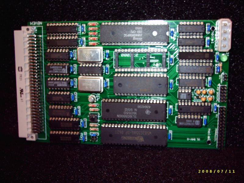
  4. N8VEM (designed by Andrew Lynch) uses a vanilla Z80, serial port with 16C550, huge SRAM 512K (mostly used as a RAM-disk), big Flash Rom 1Mb with operating system (CP/M) included, ECB bus interface, Floppy interface is an external board (new design, several boards and developers here), RTC and parallel interface (i82C55) and it's all open hardware.
  5. YASBEC also uses Z180 but the hardware details are much more elusive in the internet, the disk format suggests 3.5 inch HD drives.
  6. PROF80 uses a Z80, has a floppy interface with the UPD765, high density data separator, bit-bang serial interface, on the webpage there are more details ans schematics of other boards (graphics terminal) and upgraded version with Z180 (with FDC37C68, RTC and other goodies) some more details here.
I think after that review, I can settle on what I want for my CP/M SBC with the 8085. A 3.5 inch floppy (HD), 765 Floppy interface, 8085AH-2 @ 10.24MHz (2% overclocked) a 8256AH, 128K SRAM and 32KB ROM (with a debugger, Forth or Basic and boot). On the optional is a second serial port, a parallel port, a SD Card interface and an expansion port. I think I can skip the RTC as CP/M 2.2 doesn't need it and it's optional for CP/M 3.0 .
Front panel inputs I'd like to have a RUN/HALT/SINGLE STEP switch on the front, a RESET push-button and an interrupt push-button (maybe RST7.5 or TRAP). As for indicators a RUN/WAIT/HALT (green/yellow/red) LED, a INTR/INTA (red/green) and a HOLD/HLDA (only if there's an expansion port).

2010 "balcony carrots" grand cru

For those of you that just arrived, this blog has nothing to do with wine... today I'm talking about carrots. This year's crop of carrots from the balcony vases was about 200g, slightly less than last year's (300g), but I planted other stuff (some worked out, some didn't). Crops were delayed (about 1 month) this year due to the harsh winter. We also had a new arrival, little Luísa! She loved the carrots as finger-food... extra tasty!

She is now 9 months and moving around, she takes much interest in my books...

But most of the time she's a sweet baby...

2010-08-18

Mending Jeans

I bike to work regularly, even during winter. As a result my jeans wear off often, every time in the same place, let's call it "the saddle area". I used to take the jeans back home and ask mum to do it. She would just go to her "work room" power up her good old sewing machine and get it done in no time.


Since we decided last year to buy a sewing machine, I thought I could try and do it myself. It is very easy and hardly noticeable once the patch is made.
You will need a pair of jeans to fix, a jeans patch a bit bigger than the hole (+2cm, 1 inch) and thread.


There's a trick about the thread (thanks mum), use grey or light grey thread. Using blue thread, even if it's the same colour as the jeans will produce a noticeable patch.


Place the patch on the inside of the jeans and secure it with pins, take care to stretch both the jeans and the patch.


Load the top thread with the grey coloured thread (the under carrier is not so important), select a wide zig-zag stitch (5mm width) and reduce the length (advance) to 1 to 2mm (a bit like the bottom right stitch of figure 2 here).
Lock both fabrics under the zig-zag presser foot starting from 2cm/1 inch outside the hole to cover, sew until 2cm/1 inch the hole end. Repeat in reverse.


When you reach the place where you started, move the needle to the top most position, release the feet, move the fabrics 5mm (about the width of the stitch) to the side, press the feet and repeat until the hole is covered.


Here is the patch finished. The good news are it is hardly noticeable, the bad news are, that usually if you do this in one leg, chances are the other leg's fabric will also fail in a few weeks.